KAmod ESP32-C3 DIN
From Kamamilabs.com - Wiki

Description
KAmod ESP32-C3 DIN - Universal control module with ESP32-C3 microcontroller
The KAmod ESP32-C3 DIN board utilizes the ESP32-C3-WROOM-02U module, which enables 2.4 GHz Wi-Fi communication and is based on a microcontroller with RISC-V architecture. Furthermore, the board implements a USB interface for programming and application monitoring, an RS485 interface commonly used in automation, and an I2C interface in the Q-wire standard for easy system expansion. Additionally, the microcontroller can control 4 outputs with low-power MOSFET transistors, and the power supply circuit allows for an input voltage range of 7–32 V. The entire design fits on a small PCB tailored for the Z106 type enclosure, which can be mounted on a DIN35 rail.


Basic Parameters
- ESP32-C3 Microcontroller - 32-bit RISC-V core, max 160 MHz
- Memory size: 400 kB SRAM, 4 MB SPI Flash
- Communication: 2.4 GHz Wi-Fi, IEEE 802.11 b/g/n and Bluetooth 5 LE
- Antenna connector: U.FL type
- RS485 interface equipped with surge protection
- USB interface for programming and application monitoring (implements USB-UART function)
- Micro-buttons for reset and initiating programming mode (bootloader)
- I²C interface with 3.3 V power supply in Q-Wire standard (Qwiic, Stemma QT)
- 4 LEDs signaling: power, RS485 communication, and application-controlled status
- Goldpin header with 3.3 V power output and 7 GPIO lines
- 4 low-power outputs with N-MOSFET transistors (max 1 A)
- 2 analog inputs with voltage dividers - 12-bit ADC resolution, max input voltage 32 V
- DC power supply range: 7–32 V, current consumption up to 100 mA (module only, in active mode)
- 5 V DC power supply via USB-C connector
- Power supply, RS485 interface, and output connectors: Phoenix MC 3.81 mm type
- Compatible with Arduino IDE
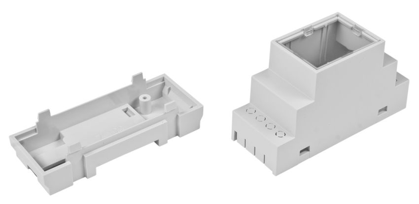
- Compact dimensions tailored for Z106 DIN35 rail enclosure (enclosure not included)
Standard Equipment
| Code | Description |
|---|---|
| KAmod ESP32-C3 DIN | Assembled and tested module |
| 2.4 GHz Wi-Fi Antenna | Antenna with U.FL connector |

Electrical Schematic
Main Schematic

Power Supply Circuit Schematic

RS485 and USB Interface Schematic

Functions Assigned to GPIO Lines
The ESP32-C3-WROOM-02U module has 15 GPIO lines. The table below describes the functions assigned to specific lines on the KAmod ESP32-C3 DIN board.
| GPIO | Function |
|---|---|
| 00 |
ADC0-0 input, routed to the IntIO pin header and connected via a 100 k/10 k divider to Output 2 |
| 01 |
ADC0-1 input, routed to the IntIO pin header and connected via a 100 k/10 k divider to Output 1 |
| 02 |
I2C clock line - SCL, connected to the IntIO header and Q-Wire connector. |
| 03 |
I2C data line - SDA, connected to the IntIO header and Q-Wire connector. |
| 04 |
Controls N-MOSFET transistor, Output No. 4 available on J8 connector |
| 05 |
Controls N-MOSFET transistor, Output No. 3 available on J8 connector |
| 06 |
Controls N-MOSFET transistor, Output No. 2 available on J8 connector |
| 07 |
Controls N-MOSFET transistor, Output No. 1 available on J8 connector |
| 08 |
Controls LED - LED08, signal active LOW |
| 09 |
Controls LED - LED09 and reads the state of the programming (PRG) button. |
| 10 |
Controls DE/RE signal of the RS485 transceiver; HIGH level activates the transmitter. Available on IntIO header |
| 18 |
USB interface D- signal |
| 19 |
USB interface D+ signal |
| 20 |
UART RX interface input, connected to IntIO header and RS485 transceiver |
| 21 |
UART TX interface output, connected to IntIO header, RS485 transceiver, and LED21 |
Low-Power Outputs
| Output | GPIO Line / state to activate |
Connector / Notes |
|---|---|---|
| 1 | GPIO 07 / H | J8-2 (OUT 1) / Active state on output - GND |
| 2 | GPIO 06 / H | J8-3 (OUT 2) / Active state on output - GND |
| 3 | GPIO 05 / H | J8-4 (OUT 3) / Active state on output - GND |
| 4 | GPIO 04 / H | J8-5 (OUT 4) / Active state on output - GND |
| COMM | - | J8-1 (COMM) connect to the positive power supply rail when controlling inductive loads (e.g., relays). |
Output circuits are based on N-MOSFET transistors with a maximum continuous current of 1 A. The outputs are protected against overvoltages generated by inductive loads, so they can directly control electromagnetic relays, small valves, electromagnets, or DC motors. The maximum voltage on the outputs must not exceed 32 V.
Connecting components to the module outputs should be done as shown in the following figure.

Analog Inputs
KAmod ESP32-C3 DIN has 2 analog inputs connected to an integrated 12-bit ADC. The analog inputs are equipped with 100 k/10 k voltage dividers, providing a division factor of 0.09 and allowing voltage measurement in a range up to approx. 32 V.
| ADC Measurement Channel | Connector / Output | Notes |
|---|---|---|
| ADC0-1 | J8-2 / OUT 1 | Shared with Output OUT 1 / max 32 V |
| ADC0-0 | J8-3 / OUT 2 | Shared with Output OUT 2 / max 32 V |

The analog inputs IN 1/2 are connected to outputs OUT 1/2. If a given output is activated, the analog reading will indicate a value close to 0. If you intend to use the analog input, you must ensure that the corresponding output is not activated.
It is not recommended to connect power supply voltage (e.g., from a PSU or battery) directly to analog inputs IN 1/2. In case of an error where the output is activated, it will be damaged. Power supply/battery voltage should be connected to IN 1/2 via a small resistor (100–1000 Ω).
The ADC integrated into the ES32-C3 module has 12-bit resolution but does not allow for precise voltage measurements due to high non-linearity, unstable offset, and imprecise reference voltage.
Wi-Fi Communication
KAmod ESP32-C3 DIN is equipped with an ESP32-C3-WROOM-02U Wi-Fi communication module. Its basic parameters are:
- Frequency band: 2.4 GHz
- Communication standard: compatible with IEEE 802.11 b/g/n
- Bluetooth communication: Bluetooth LE, Bluetooth 5, Bluetooth mesh
- Equipped with a U.FL type antenna connector

For the Wi-Fi module to function correctly, a compatible antenna must be attached via the U.FL connector located on the board.

USB Interface and Module Programming
KAmod ESP32-C3 DIN features a USB interface with a USB-C connector. Primary functions include:
- Acts as a USB-UART converter
- Used for programming the ESP32-C3-WROOM-02U module
- Enables application monitoring by sending messages via the serial interface
- Serves as an optional power supply port

Programming via the USB interface requires starting the so-called bootloader. To do this, while the KAmod ESP32-C3 DIN is connected via USB cable to a computer, perform the following sequence:
- Press and hold the RST button
- Press and hold the PRG button (LED09 will light up)
- Release the RST button but keep the PRG button pressed
- After a moment, release the PRG button.
This launches the bootloader, enabling the programming of the ESP32-C3 module, e.g., via the Arduino IDE.
RS485 Interface
KAmod ESP32-C3 DIN is equipped with an RS485 interface with the following parameters:
- ST485 transceiver
- Communication speed up to 1 Mbps
- Surge protection
GPIO line assignment is described in the table below.
| GPIO Line | RS485 Signal | Description |
|---|---|---|
| GPIO21 | TXD | Data output to the RS485 bus |
| GPIO20 | RXD | Data input from the RS485 bus |
| GPIO10 | DE/RE | Transmission direction control - HIGH (H) state activates transmission to the RS485 bus |

I2C Interface
The I2C interface is broken out as a 1 mm JST socket referred to as Q-Wire, which is compatible with Qwiic and Stemma QT standards. Additionally, a 3.3 V supply with approx. 300 mA capacity is available on the connector. Pin functions are described in the table.
| Connector/Pin | Signal Type | Description/Notes |
|---|---|---|
| Q-Wire / 1 | Supply Ground (GND) | Power ground |
| Q-Wire / 2 | 3.3 V Supply | Maximum load approx. 300 mA |
| Q-Wire / 3 | Data signal - SDA. Connected to GPIO03 |
Includes 2.2 k pull-up to 3.3 V |
| Q-Wire / 4 | Clock signal - SCL. Connected to GPIO02 |
Includes 2.2 k pull-up to 3.3 V |

JST 1 mm connectors in Q-Wire standard:


Int I/O Pin Header
On the KAmod ESP32-C3 DIN module, there is a goldpin header labeled Int I/O. Selected GPIO lines are broken out here – detailed descriptions are in the table.
| Pin | Signal Type | Description/Notes |
|---|---|---|
| Int I/O - 1 | 3.3 V Supply | Maximum load approx. 300 mA |
| Int I/O - 2 | GND | Power ground |
| Int I/O - 3 | GPIO02 | Connected to I2C Interface - SCL |
| Int I/O - 4 | GPIO03 | Connected to I2C Interface - SDA |
| Int I/O - 5 | GPIO00 | Connected to ADC0-0 converter input |
| Int I/O - 6 | GPIO01 | Connected to ADC0-1 converter input |
| Int I/O - 7 | GPIO20 | Connected to RS485 data input |
| Int I/O - 8 | GPIO10 | Connected to DE/RE signal (RS485 control) |
| Int I/O - 9 | GPIO21 | Connected to RS485 data output |

LED Indicators and Buttons
| Button | Signal Type | Function |
|---|---|---|
| RST | EN | Restarts the ESP32-C3 microcontroller and restarts the control software |
| PRG | GPIO09 | Launches bootloader if pressed during microcontroller restart |
| LED Indicator | Signal Type | Function |
|---|---|---|
| PWR | 3.3 V Power | Signals correct power supply to the module |
| LED21 | GPIO21 active LOW (L) |
Connected to RS485 data output; signals RS485 transmission |
| LED08 | GPIO08 active LOW (L) |
Can be freely controlled by application |
| LED09 | GPIO09 active LOW (L) |
Connected in parallel with the PRG button. GPIO09 line should be configured as Open Drain IN/OUT |

Power Supply
KAmod ESP32-C3 DIN should be powered with a DC voltage in the range of 7 to 32 V. The current consumption of the module itself does not exceed 100 mA during normal operation.
Alternatively, the module can be powered with 5 V DC through the USB-C connector.

Dimensions
The dimensions of the KAmod ESP32-C3 DIN module are 84.5 x 29 x 12 mm.

The board is designed to fit into a Z106 type modular enclosure mounted on a DIN35 rail.
Test Application
A test application has been developed for KAmod ESP32-C3 DIN, allowing you to check module functionality and serve as a base for expansion. The source code is available on KAMAMI-Labs GitHub:
https://github.com/KAMAMI-Labs/KAmod-ESP32-C3-DIN.git
