KAmod I2C-IOexp16
From Kamamilabs.com - Wiki

Opis
KAmod I2C-IOexp16 - Expander 16 digital I/O lines with MCP23017
The KAmod I2C-IOexp16 module contains 16 digital lines that can act as inputs or outputs. Control is via the I2C bus.
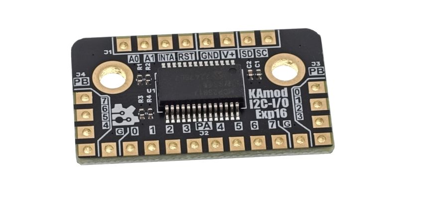
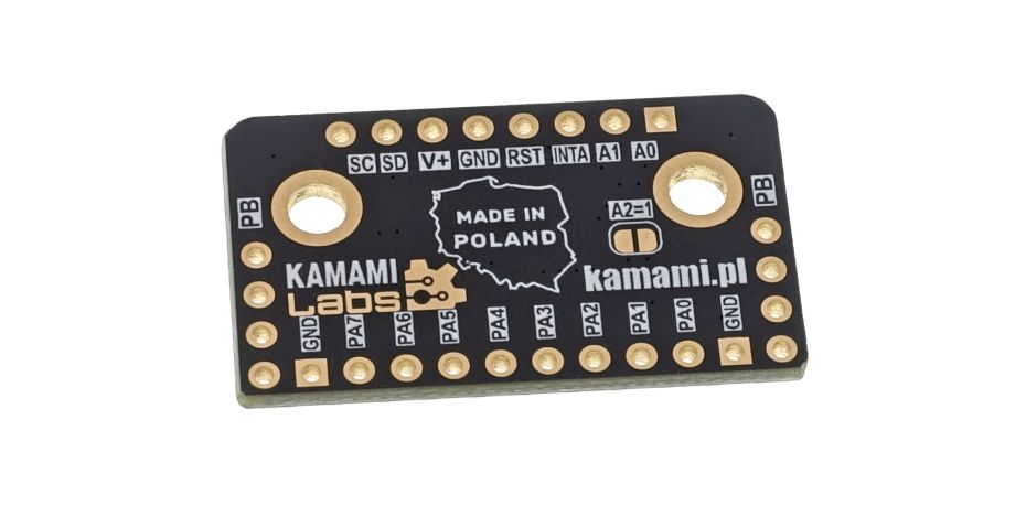
Basic features and parameters
- 16 lines that can act as inputs or outputs, with a maximum current of 20 mA
- Contains an expander type MCP23017
- Control via I2C interface with a clock speed of max. 1 MHz
- 3 address lines allow you to connect 8 modules to one I2C bus
- Interrupt output that can be assigned to the port A line
- Power supply 2...5 V
Standard Equipment
| Code | Description |
|---|---|
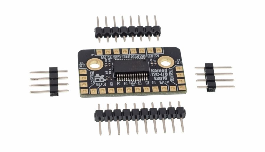
| KAmod I2C-IOexp16 |
|
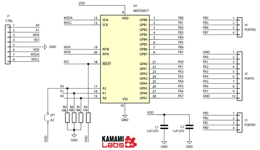
Schematic
I/O Line Layout
| Designation | Function |
|---|---|
| PA (J2) |
|
| PB (J3) |
|
| PB (J4) |
|
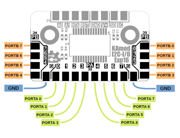
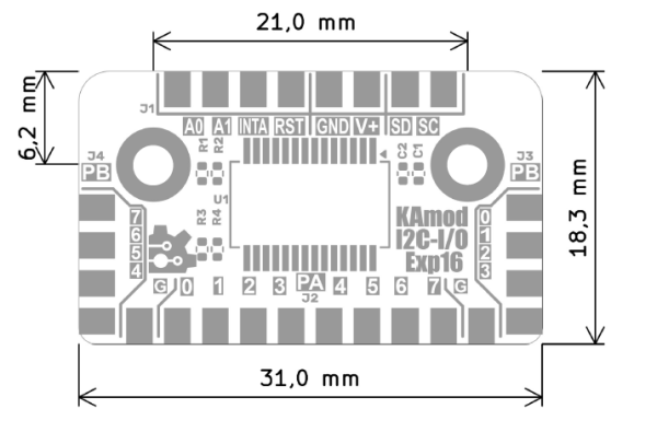
The I/O lines were led out as solder points with holes, arranged with a standard 2.54 mm pitch, right at the edges of the board. They allow for soldering wires or goldpins. The assignment of ports and leads is described in the figure below.
Each lead can be independently configured as a digital input or output. Digital outputs can be loaded with a maximum current of 20 mA. Digital inputs have independently configurable pull-up resistors and enable the generation of interrupts. Port A lines can signal the occurrence of an interrupt on an additional lead - INTA.
Control signals
| Designation | Function |
|---|---|
| SD (J1) | SDA signal (data) of the I2C interface |
| SC (J1) | SCL signal (clock) of the I2C interface |
| RST (J1) | Input that resets the system |
| INTA (J1) | Output signaling the occurrence of an interrupt on port A lines |
| A0, A1 (J1) | Inputs allowing setting the I2C interface address (bits 1 and 0). Set to logical 0 by default. |
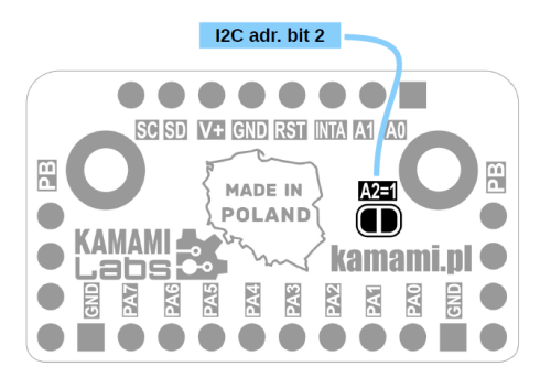
| A2 (jumper) | Installing a solder jumper allows setting bit 2 of the I2C interface address. |
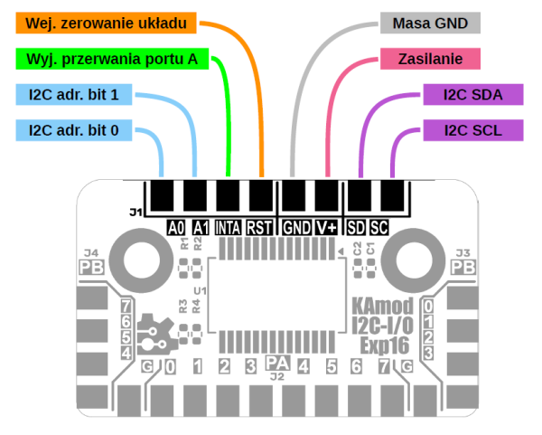
The KAmod I2C-IOexp16 module is controlled via the I2C interface, which can be clocked with a 100 kHz, 400 kHz or 1 MHz clock signal. The functions of the pins on the J1 connector are as follows:
- The I2C control interface signals are SD – SDA, and SC – SCL. They are not equipped with pull-up resistors – the control system must include the appropriate elements.
- Inputs A0, A1 allow you to set the address (bits 1 and 0) that the module connected to the I2C interface will have. By default, these inputs are connected to ground via resistors (pull-down) and take logical values of 0. Connecting the positive power supply pole to inputs A0 and A1 sets logical 1 for the lowest address bits.
- Jumper A2 located on the bottom of the module board (bottom) allows you to set bit no. 2 defining the I2C address. By default, the A2 signal is connected to ground via a resistor (pull-down) and takes the logical value of 0. Installing a solder jumper allows you to set logical 1 for bit no. 2 of the I2C interface address.
- All available I2C interface addresses are in the range 0x20...0x27.
Detailed information on communication and configuration of the MCP23017 system is available in the technical documentation of this system.
Additional signals are:
- The reset signal (RST) is used to reset the MCP23017 system on the KAmod I2C-IOexp16 board, which restores all settings to their initial state.
- The INTA output can signal an interrupt on the A port lines with an appropriate state.
Power
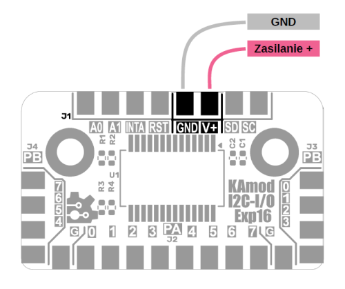
The KAmod I2C-IOexp16 module can be powered by a DC voltage of 2...5 V.
Dimensions
The dimensions of the KAmod I2C-IOexp16 board are 31x18 mm. There are 2 mounting holes on the board with a diameter of 3.2 mm.
Test program
The test program was written in the Arduino environment for the KAmodESP32 POW RS485 board. The KAmod I2C-IOexp16 module was connected via the I2C interface.
#include <Wire.h>
#include <Adafruit_MCP23X17.h>

//LED
#define LED_PIN         2
#define MY_DELAY        2000
#define TEST_LED_ON     1
#define TEST_LED_OFF    0

//I2C
#define I2C_SDA         33
#define I2C_SCL         32
#define I2C_FREQ        100000
#define MCP23017_ARD    0x20

TwoWire I2Cbus = TwoWire(0);
Adafruit_MCP23X17 MCPIO;
int i;

//-----------------------------------------------------------------
void setup() {
  Serial.begin(115200);
  Serial.println();
  Serial.println("Hello. KAmod IOexp16 test");

  pinMode(LED_PIN, OUTPUT);
  digitalWrite(LED_PIN, HIGH);

  delay(500);
  while(!I2Cbus.begin(I2C_SDA, I2C_SCL, I2C_FREQ)){
    Serial.println("I2C init failed...");
    delay(500);
  }
  while (!MCPIO.begin_I2C(MCP23017_ARD, &I2Cbus)) {
    Serial.println("MCP init failed...");
    delay(500);
  }

  Serial.println("I2C init OK");
  delay(100);
  MCPIO.pinMode(TEST_LED, OUTPUT);
}

//-----------------------------------------------------------------
void loop() {
  if (i & 1){
    digitalWrite(LED_PIN, TEST_LED_ON);
  } else {
    digitalWrite(LED_PIN, TEST_LED_OFF);
  }

  MCPIO.pinMode(i, OUTPUT);
  MCPIO.digitalWrite(i, TEST_LED_ON);
  delay(100);
  MCPIO.pinMode(i, OUTPUT);
  MCPIO.digitalWrite(i, TEST_LED_OFF);
  delay(100);

  i++;
  if (i  >= 16){
    i = 0;
  }
}