KAmod Multiplexer
From Kamamilabs.com - Wiki

Description
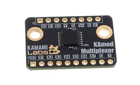
KAmod Multiplexer - Analog, 8-channel digitally controlled electronic switch
KAmod Multiplexer contains the CD4051 circuit, which is an analog, 8-channel multiplexer/demultiplexer. The circuit can operate with analog signals with an amplitude of up to 20 VPP and provides low resistance in the on state. The active channel is selected by a sequence of states on 3 digital inputs.
Basic parameters
- Power supply 3...20 V (single or symmetrical)
- Contains CD4051 chip
- 8-channel analog electronic switch: 8 inputs/outputs ↔ 1 input/output
- Can operate with analog signals with an amplitude of up to 20 VPP (however, the signal amplitude value cannot exceed the supply voltage on both the positive - VDD and negative - VEE, power supply rail)
- Typical resistance of the switched on channel is approx. 470 Ω with a 5V power supply and approx. 125 Ω at 15 V
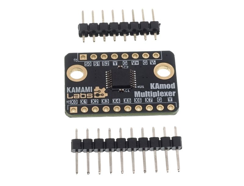
Standard Equipment
| Code | Description |
|---|---|
| KAmod Multiplexer |
|
Schematic
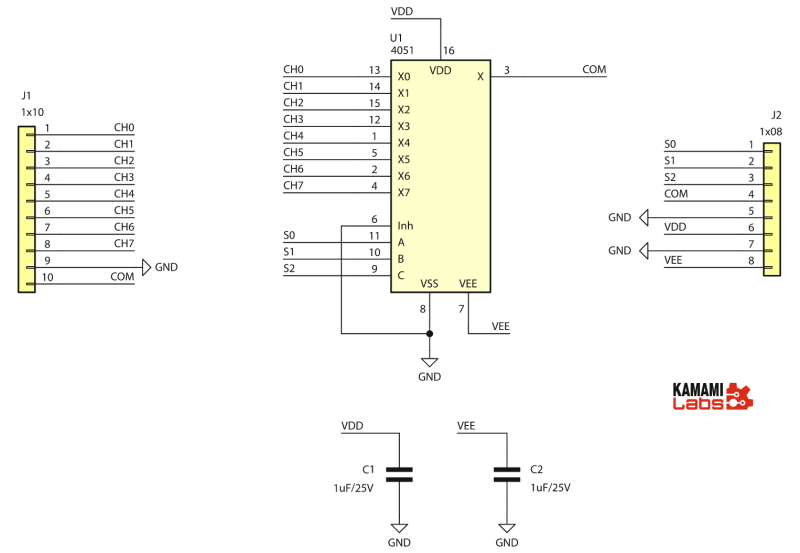
Block diagram
The figure shows the operation of an 8-channel multiplexer/demultiplexer - the CD4051 circuit. Additionally, symbols corresponding to the markings on the KAmod Multiplexer module PCB have been added.
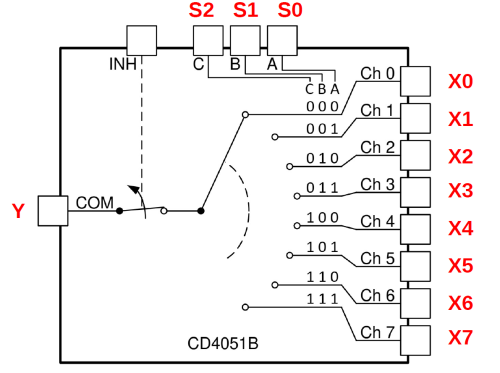
The INH signal is connected on the PCB to the power supply ground, thanks to which the Y input/output is always active.
Signal layout on the board
| Designation | Function |
|---|---|
| Y | analog input/output that is electronically connected to one of the signals X0...X7 |
| X0...X7 | 8 analog inputs/outputs |
| S0...S3 | digital control inputs in binary system |
| G | power supply ground (VSS) |
| V+ | power supply input – positive pole (VDD) |
| V- | power supply input – negative pole (VEE) for symmetrical power supply, or ground for single power supply |
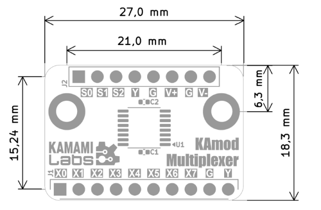
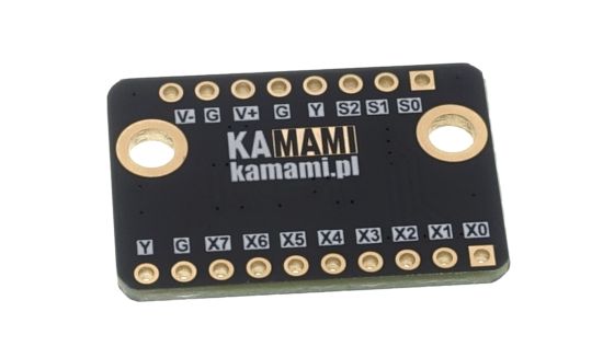
All module signals are output on two single-row connectors J1 and J2, with a pitch of 2.54 mm. The location of individual signals is described on both sides of the module board:

Some signals – Y and G appear 2 or 3 times, but they are the same signals.
Power
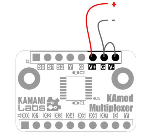
The KAmod Multiplexer module can be powered by a single, stabilized DC voltage of 3...20 V. In this case, the V+ pin requires a positive power supply pole, while the G and V- pins should be connected to the power supply ground:
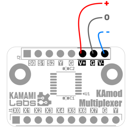
In some applications, a dual or symmetrical power supply will be required, e.g. in circuits with audio signals. In this case, a power supply with two voltages should be supplied, the sum of which will be 3...20 V. The V+ pin requires a positive power supply pole, the G pin is the power supply ground, while the V- pin requires a negative power supply. The connection diagram for such a configuration is shown in the figure below:
Dimensions
The dimensions of the KAmod Multiplexer board are 27x18.3 mm. There are 2 mounting holes on the board with a diameter of 3.2 mm.
