KAmod RS232S-ALL
From Kamamilabs.com - Wiki

Description
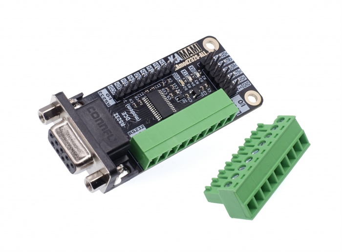
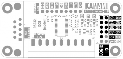
KAmod RS232S-ALL is a converter of the RS232 standard to the TTL standard, which contains all the RS232 interface signals: RXD, TXD, DTR, DSR, RTS, CTS, DCD and RI. The direction of signal conversion is assigned in such a way that it corresponds to a DCE/Modem type device (slave device, TXD is the RS232 signal input, RXD is the RS232 signal output). The converter can operate at a voltage of 3...5.5 V on the TTL side. The board has a standard DB9 connector, a Phoenix MC 3.81 connector for easy connection of non-standard wiring, and 2.54 mm goldpins for easy connection to evaluation boards.
Basic parameters
- RS232 to TTL standard converter, containing all 8 signals
- Based on MAX3238/SP3238
- Voltage on TTL side 3...5.5 V
- Maximum transmission speed: 250 kbps
- ESD protection up to 15 kV HBM on RS232 side
- Signal conversion direction assigned in such a way that it corresponds to the slave device, type DCE/Modem (TXD is RS232 signal input, RXD is RS232 signal output)
- Standard DB9 (D-SUB 9) female connector
- Phoenix MC 3.81 connector for easy connection of non-standard cabling on the RS232 side
- 2.54 mm goldpins on the RS232 side for easy connection to evaluation boards and measurements
- Power supply 3...5.5 V, approx. 20 mA
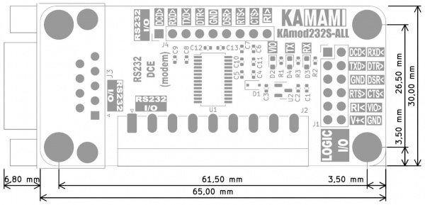
- Board dimensions 65x30 mm (72x30 with DB9 connector), height approx. 17 mm
Standard equipment
| Code | Description |
|---|---|
| KAmod RS232S-ALL | Assembled and started module |
Electrical diagram
Functional diagram
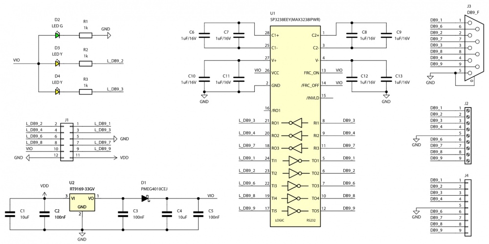
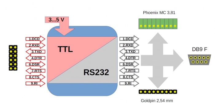
The RS232 standard is used for digital communication in serial mode, and because in addition to the data transmission line it also contains lines for controlling and controlling communication, it provides a stable connection resistant to interference. The voltages on the RS232 interface lines have values from ±7 V to ±15 V, so connecting to a classic TTL digital system, whose signals take values of 0/3.3 V or 0/5 V requires the use of a suitable converter, such as KAmod RS232S-ALL. The signal conversion direction for all 8 signals is assigned in such a way that it corresponds to the slave device - DCE/Modem. The functional diagram shows which signals act as inputs and which as outputs on the TTL and RS232 sides.
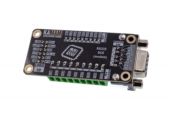
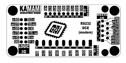
On the converter board, on the lower description layer, the exact markings of each signal on each connector have been placed:
TTL connector (LOGIC I/O)
| Connector | Function |
|---|---|
| LOGIC I/O
2x6 goldpin pins, 2.54 mm |
|
The LOGIC I/O connector allows you to connect the KAmod RS232S-ALL converter with any digital system operating with a voltage of 3...5.5 V.
The functions of the individual pins are as follows:
- pin no. 1 - TTL input; DCD signal - Data Carrier Detect (signal of detection of the carrier wave by the modem); :* pin no. 2 - TTL input; RXD signal - Receive Data Line (data stream transferred from DCE/Modem to RS232 interface);
- pin no. 3 - TTL output; TXD signal - Transmit Data Line (output of data stream sent to DCE/Modem via RS232);
- pin no. 4 - TTL output; DTR signal - Data Terminal Ready (readiness of DTE/Host device for further cooperation with DCE/Modem);
- pin no. 5 - ground, GND;
- pin no. 6 - TTL input; DSR signal - Data Set Ready (readiness of DCE/Modem for further cooperation with DTE/Host);
- pin no. 7 - TTL output; RTS signal - Request To Send (request for data transmission reported by DTE/Host);
- pin no. 8 - TTL input; CTS signal – Clear To Send (readiness to transmit reported by DCE/Modem - confirms receipt of RTS signal);
- pin no. 9 - TTL input; RI signal – Ring Indicator - "ring" signal sent by DCE/Modem.
RS232 connector type DB9
| Connector | Function |
|---|---|
| DB9
(D-SUB 9) |
|
The DB9 RS232 connector, also known as D-SUB 9, is a typical connector used to implement the RS232 interface. The DCE device, i.e. the slave device (this can be a modem or a mini printer), is equipped with a female DB9 connector. The KAmod RS232S-ALL converter also includes a female connector.
The functions of the individual pins are as follows:
- pin no. 1 - RS232 output; DCD signal - Data Carrier Detect (signal of the modem detecting the carrier wave);
- pin no. 2 - RS232 output; RXD signal - Receive Data Line (received data stream, sent from DCE/Modem);
- pin no. 3 - RS232 input; TXD signal - Transmit Data Line (data stream directed to DCE/Modem);
- pin no. 4 - RS232 input; DTR signal - Data Terminal Ready (readiness of DTE/Host for further cooperation with DCE/Modem);
- pin no. 5 - ground, GND;
- pin no. 6 - RS232 output; DSR signal - Data Set Ready (readiness of DCE/Modem for further cooperation with DTE/Host);
- pin no. 7 - RS232 input; RTS signal - Request To Send (request for data transmission reported by DTE/Host);
- pin no. 8 - RS232 output; CTS signal – Clear To Send (readiness to transmit reported by DCE/Modem - confirms receipt of RTS signal);
- pin no. 9 - RS232 output; RI signal – Ring Indicator, a "ringing" signal transmitted by the modem.
Additional RS232 connectors
| Connector | Function |
|---|---|
| Phoenix MC 3.81 mm Goldpin 1x9 2.54 mm |
|
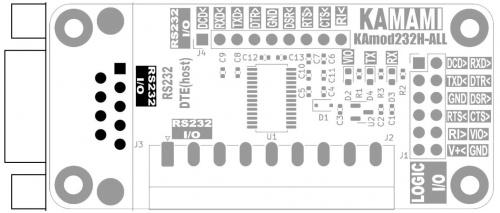
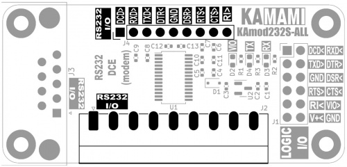
Additional connectors enable easy connection of the KAmod RS232S-ALL converter in non-standard solutions:
- Phoenix MC 3.81 mm connector enables easy connection of cables,
- Goldpin 1x9 2.54 mm connector facilitates connection of contact and evaluation boards.
The pin numbers of both connectors correspond to the pin numbers of the DB9 connector. Detailed markings can be found on the converter board.
Power
| Connector | Function |
|---|---|
| LOGIC I/O
Goldpin pins 2x6, 2.54 mm |
|
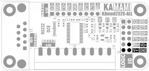
The LOGIC I/O connector contains pins that supply power to the KAmod RS232S-ALL converter
- pin no. 10 – VIO; voltage input in the range of 3...5.5 V, which will correspond to logical "1" for all signals on the LOGIC I/O connector;
- pin no. 11 – V+; allows you to connect a power supply with a voltage of 4.5...5.5 V, which goes to the 3 V voltage regulator built into the converter. Signals on the LOGIC I/O connector with a level of logical "1" will then have a voltage of 3 V, and a voltage of 3 V will be available on the VIO pin, with a current of up to 20 mA;
- pin no. 12 – ground, GND.
Power and communication signaling
| TYPE | Function |
|---|---|
| VIO TX RX |
|
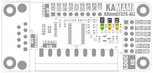
The LED marked VIO indicates the presence of the converter's power supply voltage. When a 5 V power supply is connected to the V+ contact, the diode also signals the operation of the 3 V voltage regulator.
The TX and RX diodes flash to indicate the occurrence of active states on the LOGIC I/O data lines - to the converter (RXD) and from the converter (TXD). Flashing diodes do not guarantee that the data is in the correct form. The active state on the digital inputs/outputs is the logical state "L", i.e. voltage close to 0 V.
Dimensions
The dimensions of the KAmod RS232S-ALL converter are 65x30 mm and 72x31 with the DB9 connector). The height of the module is approx. 17 mm. The diameter of the mounting holes is 3.2 mm and their arrangement is shown in the drawing.
