KAmod TPS5401
From Kamamilabs.com - Wiki

Description
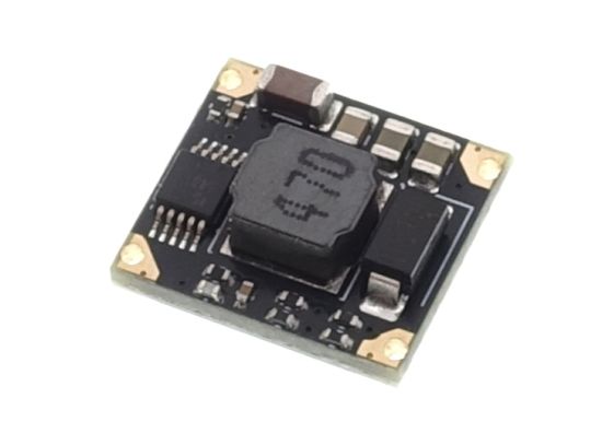
KAmod TPS5401 - Miniature, switching voltage regulator with TPS5401
KAmod TPS5401 is a small Step-Down switching regulator module based on the energy-saving TPS5401. The output voltage can be 3.3 V, 5 V or 12 V, depending on the module version. The maximum continuous output current is 0.5 A, and the input voltage can be up to 42 V. The module's pins are arranged in a 2.54 mm pitch and allow for soldering wires or golpins.
Basic parameters
- modules available with output voltage set to 3.3 V, 5V, 12 V
- continuous output current 0.5 A, with the possibility of temporary overload up to 0.8 A
- wide range of input voltage values: 4...42 V
- EN control input for switching the stabilizer on and off
- very low current consumption with unloaded output: approx. 1 mA
- very low current consumption in shutdown mode: approx. 1 uA
- converter operating frequency: 700 kHz
- gentle voltage increase when switching on the stabilizer - Soft-Start function
- possibility to set the threshold value of the input voltage, below which the stabilizer will be switched off - there will be no voltage at the output
- the PCB contains contacts arranged in a 2.54 mm pitch intended for soldering wires or goldpins
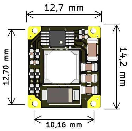
- dimensions 14.2 x 12.7 x 5 mm
Standard Equipment
| Code | Description |
|---|---|
| KAmod TPS5401 |
|
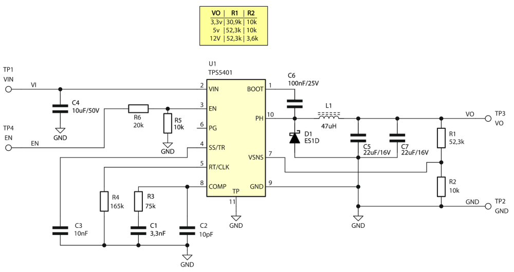
Schematic
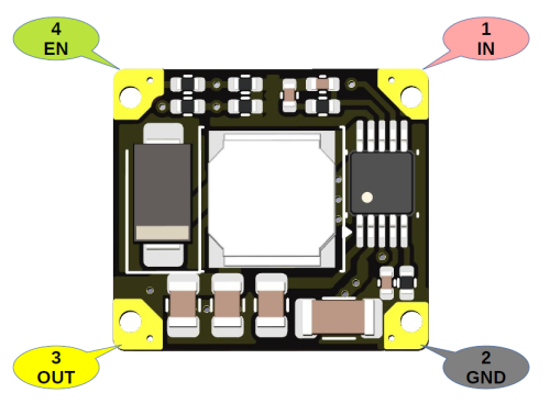
Pinout and functions
| Number and designation | Description |
|---|---|
|
1. IN |
|
|
2. GND |
|
|
3. OUT |
|
|
4. EN |
|
The drawings below show the module's pins, both in the perspective of the top view and the bottom view.
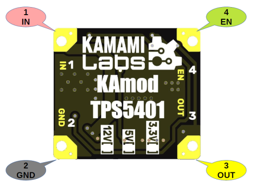
Module voltage versions
| Output voltage | Notes |
|---|---|
|
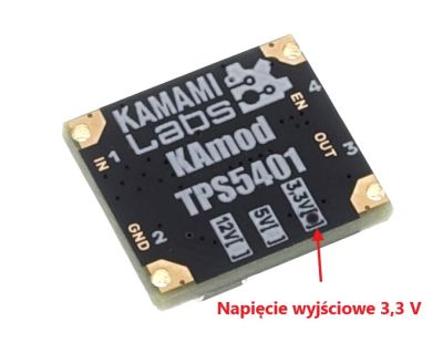
3.3 V |
|
|
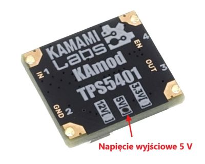
5 V |
|
|
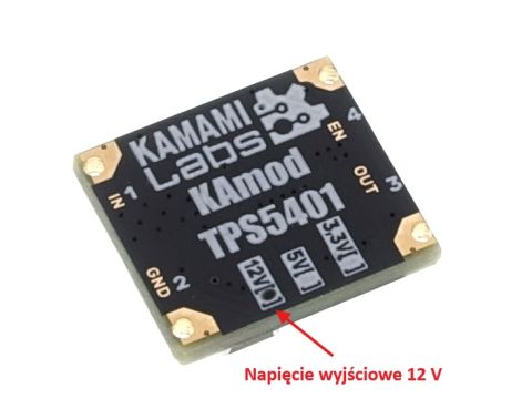
12 V |
|
The photos below show how all voltage versions are marked.
Setting the input voltage threshold
| Pin | Function |
|---|---|
|
Pin no. 4 - EN |
A positive voltage of more than 3.75 V at the EN input causes the |
The module input marked as EN is connected to the ENABLE input of the TPS5401 system via a resistive divider. This solution causes the stabilizer to be activated when the voltage at the EN input exceeds 3.75 V and, similarly, the stabilizer will be turned off when the voltage drops below this value. A detailed description of the ENABLE input operation can be found in the TPS5401 system documentation.
The EN module pin is connected to the power supply ground via a total resistance of 30 kΩ. By adding a resistor between the EN input and the positive pole of the module's power supply, the threshold value for starting the stabilizer can be changed. Example values of resistance and threshold voltage:
| Additional resistor at the EN input | Threshold voltage value |
| 20 kΩ | 6.2V |
| 68 kΩ | 12.3 V |
| 75 kΩ | 13.1 V |
Dimensions
The module board measures 14.2 x 12.7 mm. The pinout is shown in the drawing.
