KamodRPI Pico Quad SSR
From Kamamilabs.com - Wiki

Description
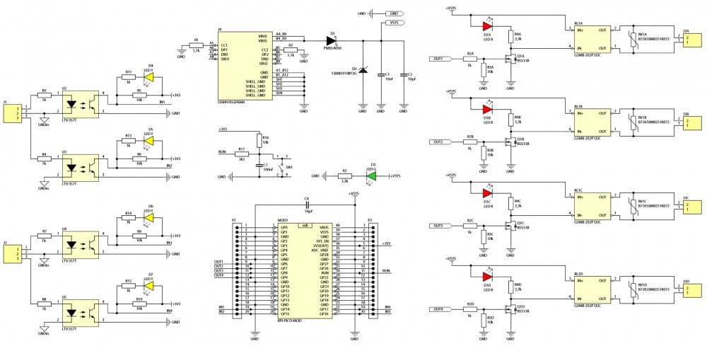
KamodRPI Pico Quad SSR is a module in the form of a shield for Raspberry Pi Pico equipped with four solid-state relays. The board also includes four digital inputs with optoisolation, a set of LEDs signaling the states of inputs and outputs, a RESET button, and a supply voltage indicator. The module will find applications in building automation (including smart home applications), robotics, industrial automation, measurement systems, laboratory installations, as well as teaching.

Basic parameters
Outputs
- 4x relay outputs - OMRON G3MB with built-in suppressors
- Factory-fitted SIOV varistors (surge current: 400 A)
- Switching method: zero
- Output load capacity:
- 0.1...2 A / 100...240 V (AC), 50...60 Hz,
- operating voltage range: 75...264 V,
- peak current: 30 A (@ 60 Hz, 1 period).
- LEDs indicating relay activation status
- 3.81 mm screw terminals (detachable)
Inputs
- 4x optoisolated inputs (LTV-357T optocouplers),
- Input voltage - active state: 5 V (4.5...9 V) DC
- LEDs indicating input status
- 3.81 mm screw terminals (detachable)
Others
- Power supply: 5 V / 400mA (min.)
- Automatic selection of power source: micro USB (RPi Pico) or USB C (J4)*
- LED indicating the presence of power supply voltage
- Built-in RESET button
- All RPi Pico lines led out to 2.54 mm (100 mil) pin connectors
- PCB dimensions: 93 x 89 mm
- * It is recommended to connect only one of the USB cables in a given moment
Standard equipment
| Code | Description |
|---|---|
| KamodRPI Pico Quad SSR |
Assembled and tested module |
Schematic
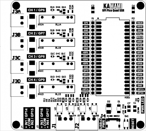
PCB view
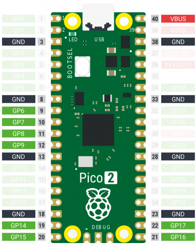
Raspberry Pi Pico GPIO Line Input and Output Assignments
| Raspberry Pi Pico Pinout | KAmodRPI Pico Quad SSR Relay (Connector) |
|---|---|
| GPIO6 | RL1A, CH 1 (J3A) |
| GPIO7 | RL1B, CH 2 (J3B) |
| GPIO8 | RL1C, CH 3 (J3C) |
| GPIO9 | RL1D, CH 4 (J3D) |
| GPIO14 | IN1 (J1, pins 1-2) |
| GPIO15 | IN2 (J1, pins 3-2) |
| GPIO16 | IN3 (J2, pins 1-2) |
| GPIO17 | IN4 (J2, pins 3-2) |
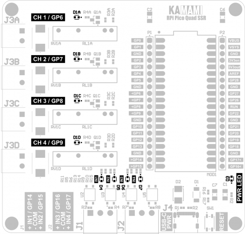
Signal LEDs
The module is equipped with 8 LEDs signaling relay activation and opto-isolated input states, as well as an additional diode indicating the presence of supply voltage.
Relay outputs
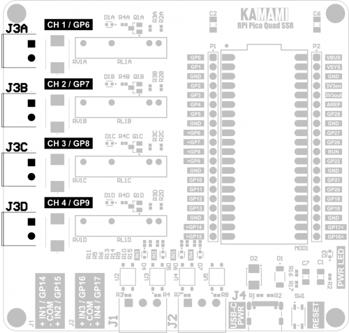
The relay contact outputs are led out to detachable screw connectors enabling the attachment of both insulated wire ends and wires with crimped sleeve terminals.
Optoisolated inputs
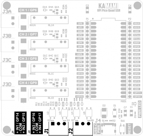
Optoisolated inputs are connected to detachable screw connectors, which allow for mounting both bare wire ends and wires with crimped ferrules. Control signals should be connected between the IN1...IN4 contact and the COM contact (belonging to the same J1 or J2 connector). The common (COM) contacts of J1 and J2 connectors are not connected, which allows for operation with sources with different ground potentials.
Application example
KamodRPI Pico Quad SSR shield with Raspberry Pi Pico module inserted.

| The Raspberry Pi Pico computer shown in the pictures is not included in the set. |
|---|
MicroPython Test Program Code
The example program turns on relays CH 1… CH 4 one by one. Then it switches to input signal control mode, in which the relay with a given number X (X=1...4) will be controlled depending on the state of input number X, for example: applying 5 V to pin 1 of connector J1 (IN1 input) will turn on relay CH 1 (J3A).
from machine import Pin
import utime

rel1 = Pin(6, Pin.OUT)
rel2 = Pin(7, Pin.OUT)
rel3 = Pin(8, Pin.OUT)
rel4 = Pin(9, Pin.OUT)

in1 = Pin(14, Pin.IN)
in2 = Pin(15, Pin.IN)
in3 = Pin(16, Pin.IN)
in4 = Pin(17, Pin.IN)

rel1.value(0)
rel2.value(0)
rel3.value(0)
rel4.value(0)


rel1.value(1)
utime.sleep(0.5)
rel1.value(0)
rel2.value(1)
utime.sleep(0.5)
rel2.value(0)
rel3.value(1)
utime.sleep(0.5)
rel3.value(0)
rel4.value(1)
utime.sleep(0.5)
rel4.value(0)

utime.sleep(2)


while 1:

 if in1.value() == 0:
 rel1.value(1)
 else:
 rel1.value(0)

 if in2.value() == 0:
 rel2.value(1)
 else:
 rel2.value(0)

 if in3.value() == 0:
 rel3.value(1)
 else:
 rel3.value(0)

 if in4.value() == 0:
 rel4.value(1)
 else:
 rel4.value(0)