Difference between revisions of "ZL30PRGv2-1"
Anna Kubacka (talk | contribs) (Created page with "__jzpdf__ Nowoczesny programator-debugger z USB obsługujący interfejsy SWD (mikrokontrolery STM32). W pełni zgodny z programatorem-debuggerem ST-Link/V2-1 firmy STMicroelec...") |
Anna Kubacka (talk | contribs) |
||
| (13 intermediate revisions by 2 users not shown) | |||
| Line 1: | Line 1: | ||
__jzpdf__ | __jzpdf__ | ||
| − | + | ||
| − | |||
<center> | <center> | ||
[[File:Zl30prgv2-1_01.jpg|none|600px|thumb|center]] | [[File:Zl30prgv2-1_01.jpg|none|600px|thumb|center]] | ||
</center> | </center> | ||
| + | ====== Description ====== | ||
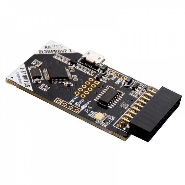
| + | An innovate programmer--debugger with the USB interface. It supports the STM32 microcontrollers thru SWD interface. ZL30PRGv2-1 is fully compatible with the STMicroelectronics ST-Link/V2-1. It also has the function of USB-UART converter. | ||
| − | + | The programmer is working with the PC using USB interface. The ZL30PRGv2-1 is supported by popular IDE's: uVision (by Keil/ARM, for STM32), IAR Embedded Workbench (by IAR, for STM32), True Studio (by Atollic, for STM32), VX-toolset for ARM Cortex-M (by TASKING, for STM32). | |
| − | |||
| − | |||
<center> | <center> | ||
| Line 14: | Line 13: | ||
</center> | </center> | ||
| − | ===== | + | ===== Paramters ===== |
| − | * | + | *embedded IDC20 female connector, |
| − | * | + | *allows to flash and debug STM32 microcontrollers |
| − | * | + | *fully compatbile with the ST-Link/V2-1 (STMicroelectronics), |
| − | * | + | *it works with: µVision (Keil), IAR Embedded Workbench (IAR), True Studio (Atollic), VX-toolset for ARM Cortex-M (TASKING), |
| − | * | + | *embedded microUSB connector, |
| − | * | + | *an USB-UART function (with pinout compatble with KAMAMI KAmodRS), |
| − | * | + | *supplied thru USB, |
| − | * | + | *possibility of firmware upgrade |
| − | * | + | *target Voltages range: |
| − | ** | + | **SWD: 1.65...3.6V, |
| − | * | + | *Working temperature range: 0...50°C. |
===== Standard equipment ===== | ===== Standard equipment ===== | ||
| Line 34: | Line 33: | ||
! style="text-align: center;"|Description | ! style="text-align: center;"|Description | ||
|- | |- | ||
| − | | style="text-align: center;"|<b> | + | | style="text-align: center;"|<b>ZL30PRGv2-1</b> |
| style="text-align: left;"| | | style="text-align: left;"| | ||
| − | * | + | *Programmer |
| + | *USB A/B-micro cable | ||
|} | |} | ||
</center> | </center> | ||
| − | ===== | + | ===== Connecting the programmer to a STM32 target device ===== |
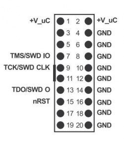
| + | SWD signals for programming and debugging the STM32 targets are present on the IDC20 connector. Its pin-out is compatbile with the industrial 20-pin JTAG standard (as illustrated on the drawings below), so the programmer could work with any STM32 evaluation boards which uses IDC20 JTAG connector (ZL27ARM, ZL30ARM, STM32Butterfly – Kamami, Keil/ARM evaluation boards, etc). | ||
<center> | <center> | ||
| − | |||
{| class="wikitable" style="width: 800px;" | {| class="wikitable" style="width: 800px;" | ||
|- | |- | ||
| − | ! style="text-align: | + | ! style="text-align: left;"|Note! |
| − | ! | + | The programmer does not support JTAG interface! |
| − | |||
|} | |} | ||
| + | </center> | ||
| + | <center> | ||
| + | [[File:Zl30prgv2-1_03.JPG|none|250px|thumb|center]] | ||
</center> | </center> | ||
| − | |||
| − | |||
<center> | <center> | ||
{| class="wikitable" style="width: 800px;" | {| class="wikitable" style="width: 800px;" | ||
|- | |- | ||
| − | ! style="text-align: left;"| | + | ! style="text-align: left;"|Note! |
| − | + | ZL30PRGv2-1 is powered from the USB connector. The supply voltage is not forwarded to the programmed/debugged target, so it needs to be supplied externally. | |
|} | |} | ||
| − | |||
| − | |||
| − | |||
| − | |||
</center> | </center> | ||
| − | |||
| − | |||
| − | |||
| − | |||
<center> | <center> | ||
| − | [[File: | + | [[File:Zl30prgv2-1_04_en.JPG|none|700px|thumb|center]] |
| − | |||
| − | |||
</center> | </center> | ||
| − | ===== | + | ===== Interfacing UART signals to the programmer ===== |
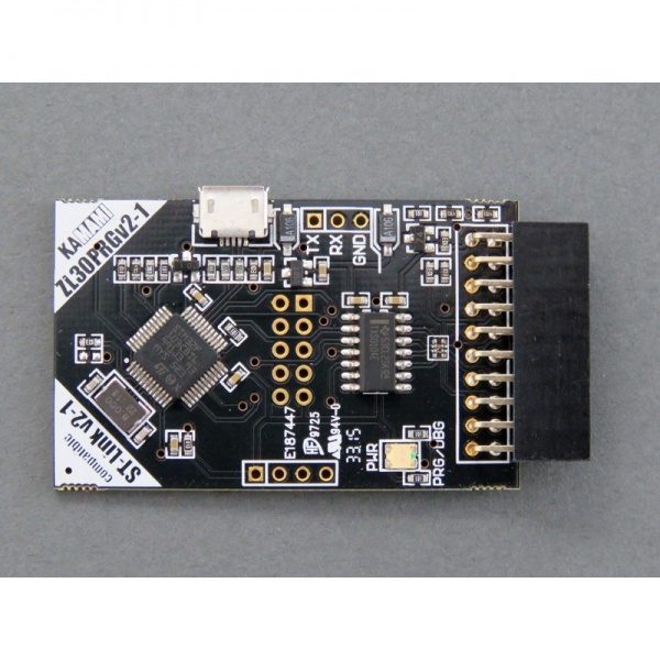
| − | + | The programmer has a Virtual COM Port (VCOM) option. RxD and TxD signals are available on the connector (as illustrated on the photo below). The drilled pads allow to solder-in Goldpin headers. By this function, the programmer can replace the KAmodRS module. | |
| − | |||
| − | |||
| − | |||
| − | |||
| − | |||
| − | |||
| − | |||
| − | |||
| − | |||
| − | |||
| − | |||
| − | |||
| − | |||
| − | |||
| − | |||
| − | |||
| − | |||
<center> | <center> | ||
| − | [[File: | + | [[File:Zl30prgv2-1_05.jpg|none|800px|thumb|center]] |
| − | |||
| − | |||
</center> | </center> | ||
| − | ===== | + | ===== Additional information ===== |
| − | + | [https://www.segger.com/products/debug-probes/j-link/models/other-j-links/st-link-on-board/ Converting ST-Llink Into a J-Link] | |
| − | |||
| − | |||
| − | |||
| − | |||
| − | |||
| − | |||
| − | |||
| − | |||
| − | |||
| − | |||
| − | |||
| − | |||
| − | |||
| − | |||
Latest revision as of 11:39, 24 September 2020

Contents
Description
An innovate programmer--debugger with the USB interface. It supports the STM32 microcontrollers thru SWD interface. ZL30PRGv2-1 is fully compatible with the STMicroelectronics ST-Link/V2-1. It also has the function of USB-UART converter.
The programmer is working with the PC using USB interface. The ZL30PRGv2-1 is supported by popular IDE's: uVision (by Keil/ARM, for STM32), IAR Embedded Workbench (by IAR, for STM32), True Studio (by Atollic, for STM32), VX-toolset for ARM Cortex-M (by TASKING, for STM32).
Paramters
- embedded IDC20 female connector,
- allows to flash and debug STM32 microcontrollers
- fully compatbile with the ST-Link/V2-1 (STMicroelectronics),
- it works with: µVision (Keil), IAR Embedded Workbench (IAR), True Studio (Atollic), VX-toolset for ARM Cortex-M (TASKING),
- embedded microUSB connector,
- an USB-UART function (with pinout compatble with KAMAMI KAmodRS),
- supplied thru USB,
- possibility of firmware upgrade
- target Voltages range:
- SWD: 1.65...3.6V,
- Working temperature range: 0...50°C.
Standard equipment
| Code | Description |
|---|---|
| ZL30PRGv2-1 |
|
Connecting the programmer to a STM32 target device
SWD signals for programming and debugging the STM32 targets are present on the IDC20 connector. Its pin-out is compatbile with the industrial 20-pin JTAG standard (as illustrated on the drawings below), so the programmer could work with any STM32 evaluation boards which uses IDC20 JTAG connector (ZL27ARM, ZL30ARM, STM32Butterfly – Kamami, Keil/ARM evaluation boards, etc).
| Note!
The programmer does not support JTAG interface! |
|---|
| Note!
ZL30PRGv2-1 is powered from the USB connector. The supply voltage is not forwarded to the programmed/debugged target, so it needs to be supplied externally. |
|---|
Interfacing UART signals to the programmer
The programmer has a Virtual COM Port (VCOM) option. RxD and TxD signals are available on the connector (as illustrated on the photo below). The drilled pads allow to solder-in Goldpin headers. By this function, the programmer can replace the KAmodRS module.


