KA-S71200-IO-Simulator
From Kamamilabs.com - Wiki

Description
KA-S71200-IO-Simulator kit helps to simulate enviroment of Siemens S7-1200 logical controller.
KA-S71200-IO-Simulator kit contains two boards:
- input, equipped with digital and analog components that simulate enviroment of PLC (from family Siemens S7-1200), and DC/DC converter that supplies all needed voltages.
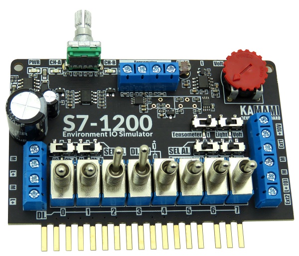
- output with LED diodes that allows to monitor outputs of PLC (family Siemens S7-1200). Diodes are driven by Nexperia LED drivers that makes sure all diodes are supplied with constant current, apart from input voltage fluctuations.

Using KA-S71200-IO-Simulator allows to verify and debug operation of your code with functionalities that allows to set:
- logical states on inputs with lever switches,
- logical states on inputs with encoder AB,
- voltage on analog inputs (ADC) from embedded: light sensor, temperature sensor and potentiometer,
- voltage on analog inputs (ADC) from tensometer or another sensor based on Wheatstone bridge,
- voltages on analog inputs (ADC) from external sensors eg. Distance, rotation speed, position sensor, and all sensors with analog outputs.
Output states are monitored with LED diodes.
Kit is highly reccomended for PLC technicians and persons who like to learn logical controllers, that want to test their applications without laborious plugging of all sensors.
| Warning!
Kit is designed to work with Siemens logical controllers from S7-1200 family that have 8/2 digital/analog inputs and maximum 6 digital outputs (in versions DC/DC/REL and DC/DC/DC). It is compatible with controllers: CPU1211C DC/DC/DC (available in special offer: 6ES7211-1AE40-0XB0 and special offer for educational purposes: 6ES7211-1AE40-0XB0) and CPU1212C (6ES7212-1AE40-0XB0). In case of desire to use with different logical controller from Siemens S7-1200 family, you should verify its compatibility with the kit. |
|---|
Parameters
The kit is dedicated to use with 24VDC supply.
Kit is desired to use with logical controllers from Siemens S7-1200 family, equipped with maximum 8/2 digital/analog inputs and maximum 6 outputs (versions DC/DC/REL and DC/DC/DC).
Output module:
- Module dedicated to work with PLC from Siemens S7-1200 family
- Recommended PLC controllers:
- CPU1211C DC/DC/DC (6 inputs/4 outputs)
- CPU1211C DC/DC/REL (6 inputs/4 outputs)
- CPU1212C DC/DC/DC (8 inputs/6 outputs)
- CPU1212C DC/DC/REL (8 inputs/6 outputs)
- Supports 8 digital channels DI.x and 2 analog channels AI.x
- Golden plated contacts, ensuring good connection with screw connectors of PLC
- Allows to simulate digital sensors with two-state lever switches
- Equipped with two-way digital rotary encoder AB
- Allows to test capabilites of AD converter with embedded:
- Wheatstone’s converter (eg. For tensometer, gain 1000V/V)
- temperature sensor MCP9700, with output voltage scaled to PLC measurement range (+5~+105°C)
- potentiometer (voltage on PLC input: 0…10VDC)
- photoresistor (voltage on PLC input: 0…10VDC)
- connectors for external sensors with analog outputs (maximum voltage on Ext1 and Ext2 inputs is 10VDC)
- Screw connectors for input voltage 24 VDC and external sensors (+24VDC and +10VDC on sensor connector for supplying the sensors)
- Included spacers to avoid stress and damaging screw connectors of controller.
LED module:
- Designed for PLC with RLY or DC outputs (chosen with switch)
- Allows to represent states of 6 outputs DQ.x
- Board connectors are gold-plated, ensuring good contact with screw connectors of controller
- Screw connectors for input voltage 24 VDC
| Module is verified to be compatible with:
CPU1211C DC/DC/DC (available in special offer: 6ES7211-1AE40-0XB0)
|
Included
| Code | Description |
|---|---|
| KA-S71200-IO-Simulator |
|
Method of connecting with PLC controller
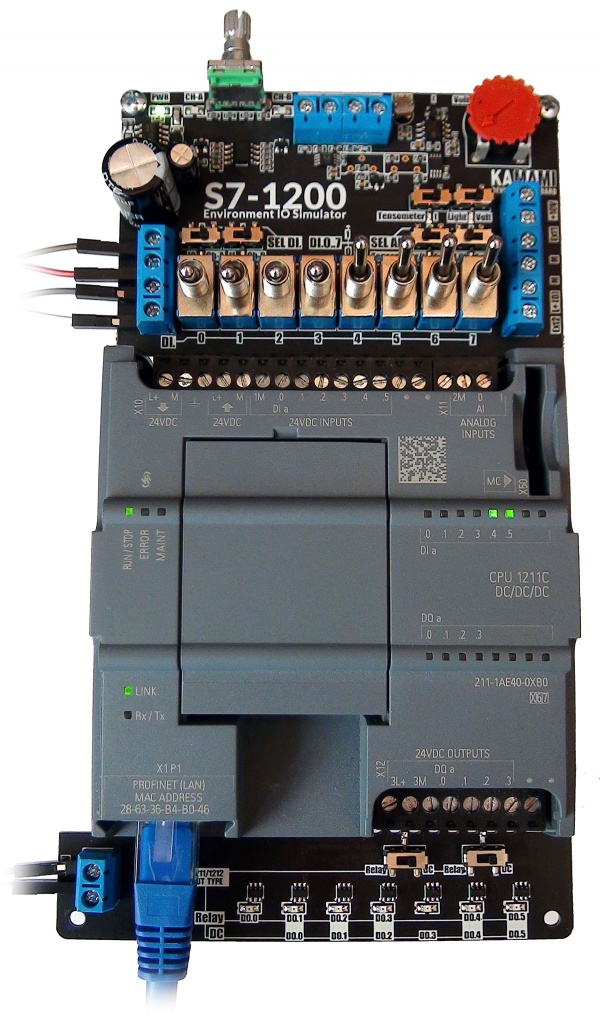
KA-S71200-IO-Simulator with CPU1211C DC/DC/DC controller
Screw connectors (supply voltage)
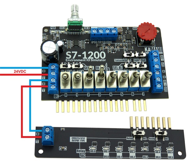
The input plate is equipped with four screw connectors for power supply, the LED board has two such connectors. The contacts marked "L +" and "M" are used to connect and transfer power between the modules. The double screw connection on the left allows:
- [upper] - connecting power to the simulator module and at the same time powering the PLC
- [lower] - transfer of power to the LED module using wires
Screw connections (tensometer, Wheatstone bridge)
The kit is equipped with an integrated tensometer conditioner, which converts the signal from the bridge to a voltage in the range of 0...10VDC.
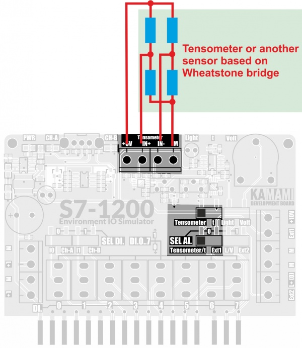
Tensometer or other sensor with differential output should be connected to the IN + and IN- terminals and + 5V and M supply lines.
The conditioner track gain is 1000V/V. In the equilibrium state of the bridge, the voltage at the conditioner output is + 5V, which allows two-way measurement of forces (in the case of a tensometer) or other quantities.
Screw connections (external sensors)
The input board of the kit is equipped with a set of screw connectors enabling connecting external sensors with analog outputs to the tested PLC.
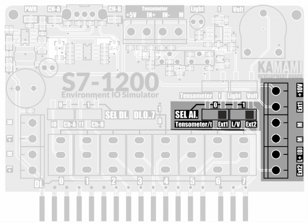
The Ext1 and Ext2 inputs are not equipped with conditioners, the voltages are fed directly to the PLC analog inputs:
- Ext1 - to the AI.0 input if the selector SEL AI.0 is in the Ext1 position,
- Ext2 - to the AI.1 input if the selector SEL AI.1 is in the Ext2 position.
| Connector | Description |
|---|---|
| Ext2 | Analogue input of external sensor, voltage is applied to PLC input AI.0 (if SEL AI.0 selector is in Ext1 position).
Input voltage range 0...10VDC. |
| L+ (O) | 24VDC voltage output from the power supply supplying the controller. |
| M | Power grounds. |
| Ext1 | Analogue input of the external sensor, voltage is applied to the PLC input AI.1 (if the selector SEL AI.1 is in the Ext1 position).
Input voltage range 0 ... 10VDC. |
| +10V | 10 VDC stabilized voltage output from the built-in power supply unit.
Maximum load capacity 100 mA. |
Switches on the input board
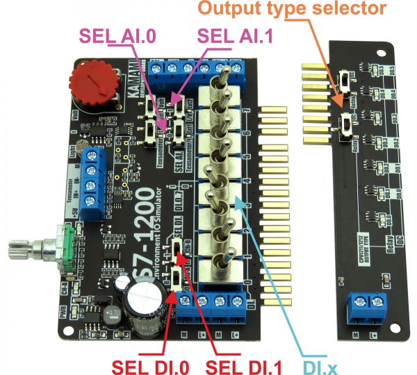
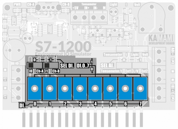
The KA-LOGOS71200-IO-Simulator board is equipped with toggle switches marked DI.0..DI7, setting the selected digital state "0" or "1" on individual digital inputs DI.x of the PLC controller.
| Warning! When using the CPU1211 controller with 6 inputs, the DI.6 and DI.7 lever switches will not be used. |
|---|
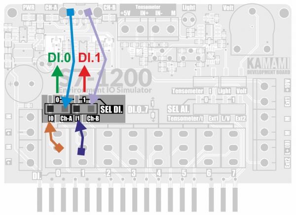
SEL DI.0 and SEL DI.1 selectors are used to connect DI.0 and DI.1 toggle switches DI.0 and DI.1 or encoder outputs - respectively:
- DI.0 - encoder A channel
- DI.1 - encoder B channel
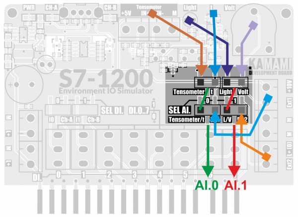
The SEL AI.0 and SEL AI.1 selectors are used to select the signal source fed to the AI inputs:
- SEL AI.0 allows you to choose between sensors:
- Built-in AFE tensometer/temperature sensor
- Ext1 external sensor input
- SEL AI.1 allows you to choose between sensors:
- Light sensor/potentiometer
- Ext1 external sensor input
| Switch | Position | Description |
|---|---|---|
| DI.0…DI7 | 0 | Logic state "0" on the corresponding DI.x line |
| 1 | Logic "1" state on the corresponding DI.x line | |
| SEL AI.0 | Tensometer/t | You can connect a tensometer output or analog temperature sensor output to input AI.0 |
| Ext1 | The AI.0 terminal is connected to the Ext1 screw terminal of the external sensor | |
| SEL AI.1 | L/V | You can connect the light sensor output or the potentiometer slider to the AI.0 input |
| Ext2 | The AI.1 terminal is connected to the Ext1 screw terminal of the external sensor | |
| Sensor selector | Tensometer | The SEL AI.0 is connected to the tensometer conditioner output |
| t | The output of the analog temperature sensor is connected to the SEL AI.0 selector | |
| Sensor selector | Light | The light sensor output is connected to the SEL AI.1 selector |
| Volt | The potentiometer slider is connected to the SEL AI.1 selector | |
| SEL DI.0 | IO | DI.0 switch is connected to the DI.0 input of the controller |
| Ch-A | The encoder channel A is connected to the DI.0 input of the controller | |
| SEL DI.1 | IO | DI1 switch is connected to the DI.1 input of the controller |
| Ch-B | The encoder B channel is connected to DI.1 input of the controller |
Temperature sensor
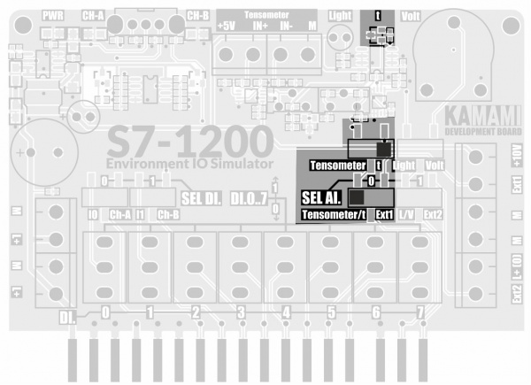
On the input board there is a temperature sensor with analog output (MCP9700AT-E/TT with 10V/V amplifier). The amplifier output voltage for the measuring range +5...+105°C is in the range of 0...10VDC.
Light sensor
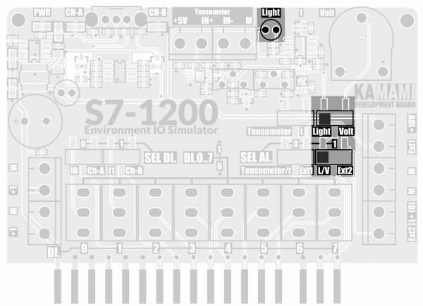
The input board has a light intensity sensor with an analog output. The voltage at its output varies in the range of 0 ... + 10VDC, its value increases as the light intensity on the sensor increases.
Encoder
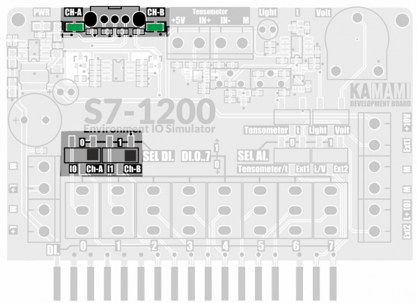
The input board is equipped with a two-phase AB encoder, which via the forming system (Schmitt trigger) provides signals to the PLC inputs:
- DI.0 – encoder A channel
- DI.1 – encoder B channel
The states of the encoder outputs A and B are monitored by two LEDs.
The encoder is connected to the PLC using the SEL DI.0 and SEL DI.1 selectors.
Output board (output states monitor)
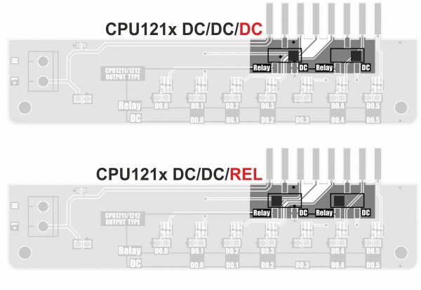
Depending on the state of the selectors installed on the output board, its configurations can be adapted to PLCs with transistor (DC / DC / DC) or relay (DC / DC / REL) outputs.
Depending on the type of outputs, the LED monitoring functions change according to the descriptions on the module board.
| Warning! When using the CPU1211 controller, which has 4 outputs, the LEDs monitoring the DO.4 and DO.5 output states will not be used. |
|---|
Test program
We provide a simple test program prepared in the TIA Portal 15.1 environment in versions for CPU1211C and CPU1212C controllers.
The program allows you to test all the peripheral elements of the set, the role of test selectors is played by switches DI.4 and DI.5 according to the table below.
Functional tests included in the test program
| DI.4 | DI.5 | Test |
|---|---|---|
| 0 | 0 | Verification of correct operation of DI.x input adjusters (x = 0..5) |
| 0 | 1 | Verification of the operation of the light sensor and potentiometer (input AI.1) |
| 1 | 0 | Verification of Wheatstone bridge operation and temperature sensor (AI.0 input) |
| 1 | 1 | Encoder operation verification |
A detailed description of the tests is available in documentation.
Spacers
The two spacers included in the kit should be mounted to the KA-S71200-IO-Simulator board to prevent board stress (and the associated excessive exploitation of the controller screw connections) when operating the module.