TIBBOcomp

Contents
Description
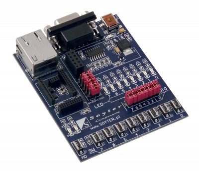
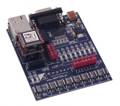
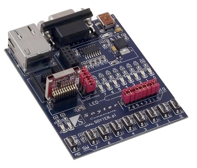
TIBBOcomp is a base board that allows easy start with miniature programmable Ethernet modules and a WiFi network. It has an embedded converter RS232 voltage levels, buttons and LEDs of any purpose.
Basic features
- Power supply 5 V via mini USB connector
- Embedded voltage level converter RS232
- 8 LEDs and 8 buttons are available to the user
- 3 status LEDs including power supply signaling
- 9-pin RS232 and RJ45 female socket
- Possibility to install Tibbo modules: EM500, EM1202 and GA1000
Standard equipment
| Code | Description |
|---|---|
| TIBBOcomp |
|
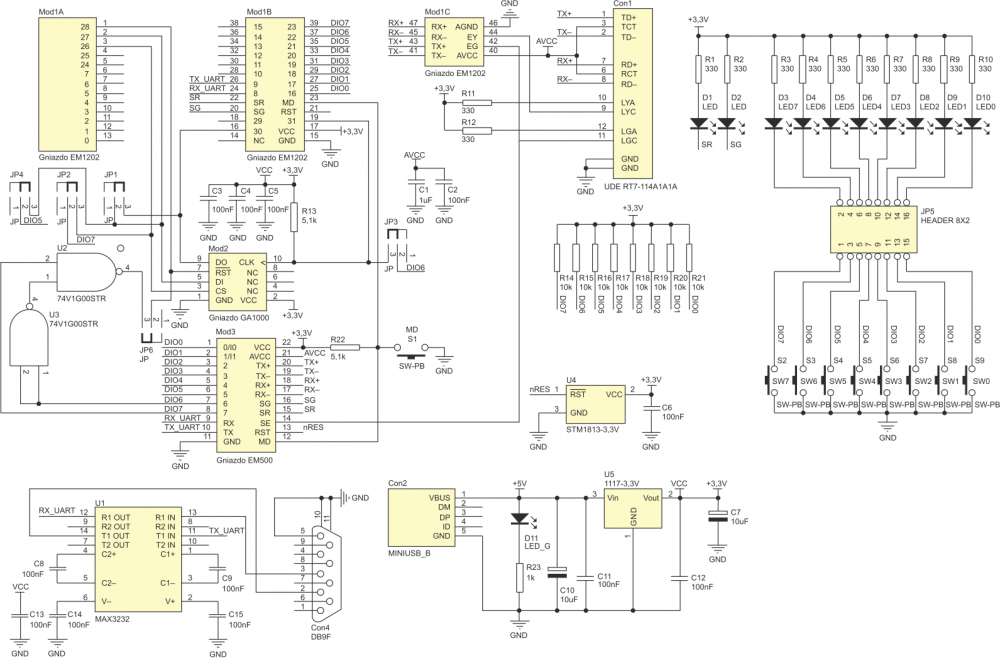
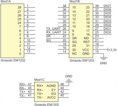
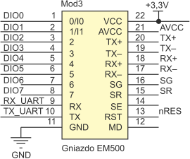
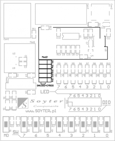
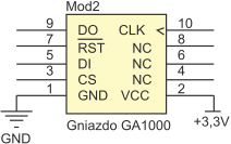
Schematic
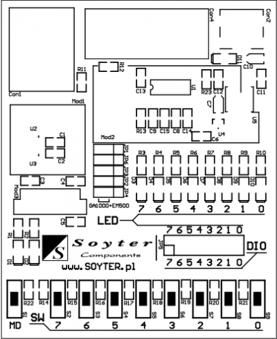
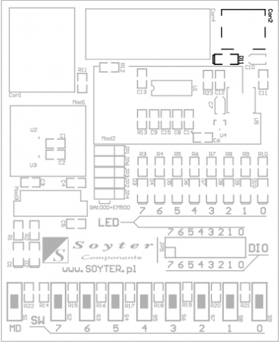
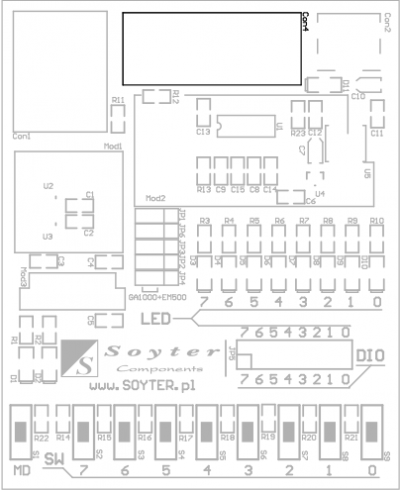
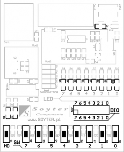
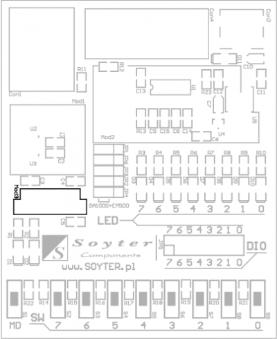
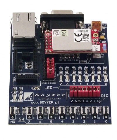
View of board
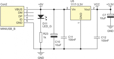
Mini USB connector (power supply)
This connector is used only to power the TIBBOcomp board. All necessary voltage converters are already placed on the board of the development kit.
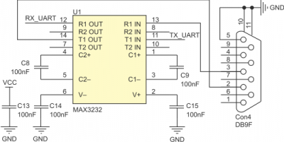
RS232 connector
The board is equipped with a DB9 RS232 connector together with an embedded voltage level converter that make possible to connect selected Ethernet module via a serial port to a PC. Through the serial port we also have the possibility of programming Ethernet modules.
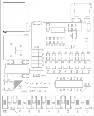
RJ45 connector
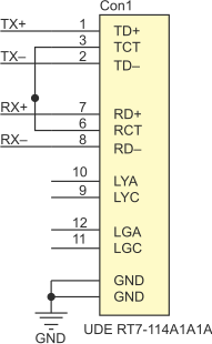
The board is equipped with an RJ45 connector to connect the EM500 or EM1202 module to the Ethernet network. Through this socket, you can also configure the network module.
LEDs and buttons
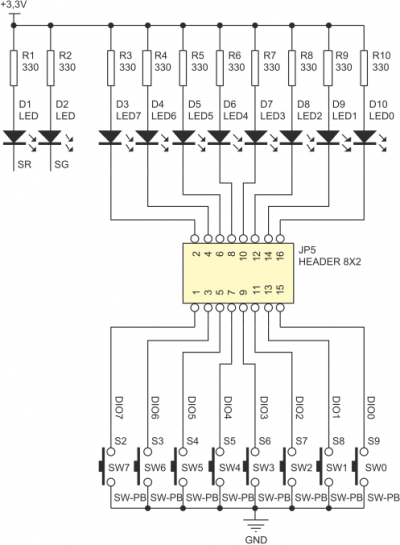
The board has been equipped with 8 LEDs and 8 buttons of any purpose, which are connected to the module GPIO ports. In addition, each LED can be physically disconnected by removing the jumper from the JP5 connector. Diodes D1 and D2 are status diodes and diode D11 indicates power supply voltage of the board.
EM1202 module connector
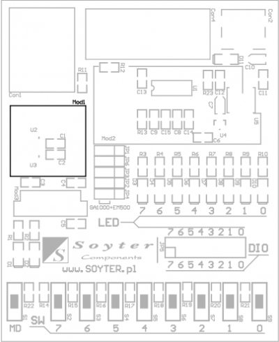
Mod1 connector it is used to connect a programmable Ethernet EM1202 module.
EM500 module connector
Mod3 connector is used to connect EM500 module.
GA1000 module connector
Mod2 connector is used to connect the WiFi module (GA1000), which can cooperate with the programmable EM1202 or EM500 Ethernet module, increasing the capabilities of these modules to work in a wireless network. Connecting the GA1000 module to the EM500/1202 module requires the setting of jumpers JP1, JP2, JP3, JP4, JP6 in the position GA1000+EM500.
